Comprehensive and Local Cooling Analysis of molds
(for fast-cycling, Class I and generic
injection molds when cycle time and quality count)
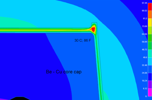
Our Cooling Analysis projects scientifically close the loop among a) computed Minimum Cycle Time, b) specified Tolerance Control of part and c) required Size, Number, and Location(s) of Cooling Channels; the size(s) and location(s) of cooling channels are specified for the mold designer within an accuracy of five thousandths of an inch. This method eliminates the guesswork and its high error possibility regarding the placement of cooling channels and the anticipated effect of resultant mold temperature distribution on cycle time and part quality. During the Cooling analysis work the required circuit and total coolant flow rate (GPM) and temperature are compared/matched to those of molding plant to achieve the required part quality (tolerance, warpage control) and minimum cycle time; we even include the connecting rubber hoses (if any) in the calculations. The temperature distribution in the core, part and cavity is evaluated by using FEA/Transient Thermal, non-linear cooling analysis; the results of the Local Cooling Analysis, focusing on the corner of Be-Cu core cap are shown in Fig. 1. The tabulated results of Comprehensive Cooling Analysis are shown in Table 1 for the mold designer and setup personnel; similar data were used for the design of the cooling system of a mold cycling at 4 . 8 sec, producing a packaging application.
Fig. 1. Local FEA/TT Cooling Analysis: temperature distribution (isotherms) at 3.1 sec after start of injection, at the beginning of mold opening.
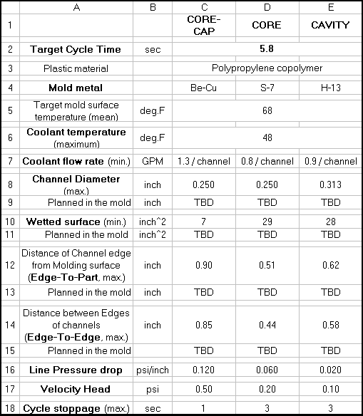
Table 1. Comprehensive Cooling Analysis: cooling system parameters for mold design and processing.